| DSS | ||||||||||||||||||
| Reference | MWL | Safety coefficient | Diameter | ø | P | Standard L1 | N.m FootLBS | S | A | B | C | D | E | F | G | Weight | ||
| DSS M 24 | 4.5 TO | 5 | M24 (x3) | 36 | 160 | 19 | 61 | 31 | 70 | 104 | 73 | 145 | 29 | 5.4 kg | ||||
| DSS M 30 | 7.3 TO | 5 | M30 (x3.5) | 45 | 250 | 19 | 61 | 31 | 70 | 104 | 73 | 145 | 29 | 5.5 kg | ||||
| DSS M 33 | 8 TO | 5 | M33 (x3.5) | 50 | 250 | 19 | 61 | 31 | 70 | 104 | 73 | 145 | 29 | 5.5 kg | ||||
| DSS M 36 | 10 TO | 5 | M36 (x4) | 54 | 320 | 19 | 61 | 31 | 70 | 104 | 73 | 145 | 29 | 5.5 kg | ||||
| DSS M 36×3 | 10 TO | 5 | M36 (x3) | 54 | 320 | 19 | 61 | 31 | 70 | 104 | 73 | 145 | 29 | 5.5 kg | ||||
| DSS M 39 | 10 TO | 5 | M39 (x4) | 58 | 320 | 19 | 61 | 31 | 70 | 104 | 73 | 145 | 29 | 5.7 kg | ||||
| DSS M 42 | 12.5 TO | 5 | M42 (x4.5) | 63 | 400 | 19 | 61 | 31 | 70 | 104 | 73 | 145 | 29 | 5.8 kg | ||||
| DSS M 42×3 | 12.5 TO | 5 | M42 (x3) | 63 | 400 | 19 | 61 | 31 | 70 | 104 | 73 | 145 | 29 | 5.8 kg | ||||
| DSS M 45 | 15 TO | 4 | M45 (x4.5) | 63 | 400 | 19 | 61 | 31 | 70 | 104 | 73 | 145 | 29 | 5.9 kg | ||||
| DSS M 48 | 20 TO | 4 | M48 (x5) | 68 | 600 | 19 | 79 | 38 | 90 | 125 | 91 | 184 | 36 | 11 kg | ||||
| DSS M 48×3 | 20 TO | 4 | M48 (x3) | 68 | 600 | 19 | 79 | 38 | 90 | 125 | 91 | 184 | 36 | 11 kg | ||||
| DSS M 48×4 | 20 TO | 4 | M48 (x4) | 68 | 600 | 19 | 79 | 38 | 90 | 125 | 91 | 184 | 36 | 11 kg | ||||
| DSS M 52 | 20 TO | 4 | M52 (x5) | 68 | 600 | 19 | 79 | 38 | 90 | 125 | 91 | 184 | 36 | 11.2 kg | ||||
| DSS M 56 | 25 TO | 4 | M56 (x5.5) | 78 | 600 | 19 | 79 | 38 | 90 | 125 | 91 | 184 | 36 | 11.3 kg | ||||
| DSS M 56×4 | 25 TO | 4 | M56 (x4) | 78 | 600 | 19 | 79 | 38 | 90 | 125 | 91 | 184 | 36 | 11.4 kg | ||||
| DSS M 64 | 32.1 TO | 4 | M64 (x6) | 90 | 600 | 19 | 79 | 38 | 95 | 125 | 91 | 184 | 36 | 12.2 kg | ||||
| DSS M 64×4 | 32.1 TO | 4 | M64 (x4) | 90 | 600 | 19 | 79 | 38 | 95 | 125 | 91 | 184 | 36 | 12.2 kg | ||||
| DSS M 72 | 25 TO | 4 | M72 (x6) | 90 | 600 | 19 | 79 | 38 | 95 | 125 | 91 | 184 | 36 | 14 kg | ||||
| DSS M 72×4 | 25 TO | 4 | M72 (x4) | 90 | 600 | 19 | 79 | 38 | 95 | 125 | 91 | 184 | 36 | 14 kg | ||||
| DSS M 80 | 32.1 TO | 4 | M80 (x6) | 90 | 600 | 19 | 79 | 38 | 95 | 125 | 91 | 184 | 36 | 15 kg | ||||
| DSS M 90 | 32.1 TO | 4 | M90 (x6) | 90 | 600 | 19 | 79 | 38 | 95 | 125 | 91 | 184 | 36 | 15.5 kg | ||||
| DSS M 100 | 32.1 TO | 4 | M100 (x6) | 90 | 600 | 19 | 79 | 38 | 95 | 125 | 91 | 184 | 36 | 16.5 kg | ||||
| DSS U 100 | 10,000 LBS | 5 | UNC 1″-8 | 36 | 160 | 19 | 61 | 31 | 70 | 104 | 73 | 145 | 29 | 5.4 kg | ||||
| DSS U 125 | 14,000 LBS | 5 | UNC 1″1/4-7 | 45 | 200 F.L | 3/4″ | 61 | 31 | 70 | 104 | 73 | 145 | 29 | 5.4 kg | ||||
| DSS U 138 | 20,000 LBS | 5 | UNC 1″3/8-6 | 54 | 300 F.L | 3/4″ | 61 | 31 | 70 | 104 | 73 | 145 | 29 | 5.4 kg | ||||
| DSS U 150 | 20,000 LBS | 5 | UNC 1″1/2-6 | 54 | 300 F.L | 3/4″ | 61 | 31 | 70 | 104 | 73 | 145 | 29 | 5.4 kg | ||||
| DSS U 200 | 50,000 LBS | 4 | UNC 2″-4 1/2 | 76 | 450 F.L | 3/4″ | 79 | 38 | 90 | 125 | 91 | 184 | 33 | 11.1 kg | ||||
| DSS U 250 | 55,000 LBS | 4 | UNC 2″1/2-4 | 90 | 600 | 19 | 79 | 38 | 95 | 125 | 91 | 184 | 36 | 12.2 kg | ||||
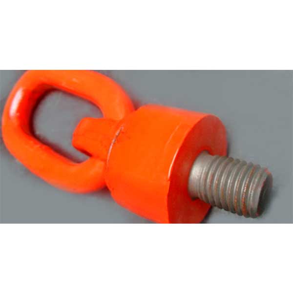
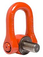
Universal elevation eyebolts
DSS
Recommendations
Unwinding
The coil should be breaked while unwinding so that the wire rope comes out with a certain pressure and does not turn on its axis. This prevents bumps and kinks. If the coil is not equipped with brakes, then an operator should stop it..

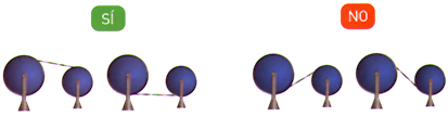
Transport between coils
When the wire rope is carried from a full coil to an empty one or to a machine drum, this should be done from the upper or lower part of both, but never from the upper part of one coil and the lower part of the other, or vice versa.
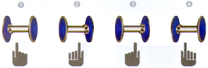
Wire rope winding
The wire rope winding on the machine drum must be carried out correctly so that there are no spires overlapping and cross-linking, which would crush and distort the cords. The following figures represent the four cases that could effectively take place:
- Right torsional wire winding at the upper part of the drum.
The mooring point should be located on the left side of the drum. - Right torsional wire winding at the lower part of the drum.
The mooring point should be located on the right side of the drum. - Left torsional wire winding at the lower part of the drum.
The mooring point should be located on the right side of the drum. - Left torsional wire winding at the lower part of the drum.
The mooring point should be located on the left side of the drum.
We do not recommend winding the wire around the drum in several layers, but if so, this technique is applied for the first layer of winding.
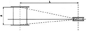
Deflection angle
The deflection angle is that formed by the wire from the first fixed pulley on the edge of the winding drum. It should not exceed 1º 30'.
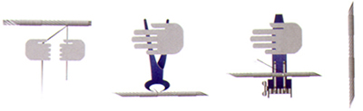
Wire cutting
Cutting with shears or scissors. Before cutting, wires are to be tied together on both sides of the cutting area. The number of ties, the width and the distance between them depend on the wire diameter (see table). It is key to avoid longitudinal tilts among the different cord layers, since, in that case, those which have moved the least will bear the greatest part of the load, and there is the risk of breakage.
| Tie characteristics | ||||
| Wire rope diameter | No. of ties on each side of the cut |
Tie length |
Distance between ties |
Wire diameter rec. iron piece to be used (mm) |
| Up to 12 | 3 | 12 | 15 | 0,5 to 0,8 |
| 13 to 20 | 3 | 25 | 40 | 1 to 1,5 |
| 21 to 30 | 4 | 40 | 50 | 1,2 to 2,2 |
| 31 to 40 | 4 | 50 | 50 | 1,8 to 3 |
| 41 to 50 | 4 | 75 | 50 | 2,2 to 3,2 |
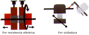
Recommended cuttings
To cut antitwisting wire ropes, we recommend cutting by electric resistance or by welding.
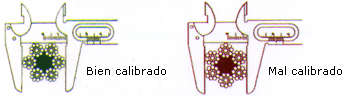
Calibration
For calibration, the measuring device must be properly used.