Chain Slings |
Loads – Single-Leg Slings | Loads – Multi-Leg Slings | ||||||
 |
 |
|||||||
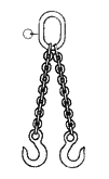
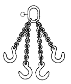
| Number of legs, n | – | – | – | 2 legs | 3 & 4 legs | |||
| Inclination angle in relation to the vertical, ß | – | – | – | ß>45º | 45º>ß>60º | ß>45º | 45º>ß>60º | |
| Angle between opposite legs, a | – | – | – | a>90º | 90º>a>120º | a>90º | 90º>a>120º | |
| Factor to calculate Maximum Working Load (MWL), f=n.cosß | 1 | 0.8 | 2 | 1.4 | 1 | 2.1 | 1.5 | |
| Nominal Dimension | MAXIMUM WORKING LOAD MWL (kg) EN 818-4, safety factor 4:1 | |||||||
 |
(mm) | Balance-loaded Chain Slings | ||||||
| 6 | 1,120 | 896 | 2,240 | 1,600 | 1,120 | 2,360 | 1,700 | |
| 7 | 1,500 | 1,200 | 3,000 | 2,120 | 1,500 | 3,150 | 2,240 | |
| 8 | 2,000 | 1,600 | 4,000 | 2,800 | 2,000 | 4,250 | 3,000 | |
| 10 | 3,150 | 2,520 | 6,300 | 4,250 | 3,100 | 6,700 | 4,750 | |
| 13 | 5,300 | 4,240 | 10,600 | 7,500 | 5,300 | 11,200 | 8,000 | |
| 16 | 8,000 | 6,400 | 16,000 | 11,200 | 8,000 | 17,000 | 11,800 | |
| 19 | 11,200 | 8,960 | 22,400 | 16,000 | 11,200 | 23,000 | 17,000 | |
| 22 | 15,000 | 12,000 | 30,000 | 21,200 | 15,000 | 31,500 | 22,400 | |
| 26 | 21,200 | 16,960 | 42,400 | 30,000 | 21,200 | 45,000 | 31,500 | |
| 32 | 31,500 | 25,200 | 63,000 | 44,100 | 31,500 | 67,000 | 47,250 | |
Information on Chain Slings
MAXIMUM WORKING LOAD
Safety Factor. To calculate the Maximum Working Loads stated in the tables, a Safety Factor = 4 has been applied.
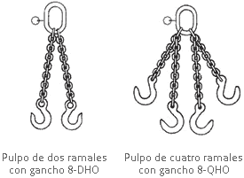
Symmetrical Load. It is assumed that in 3- and 4-leg chain octopus, the load is supported by a maximum of 3 legs if the following is true:
- The center of gravity of the load is centered on the geometry of the octopus.
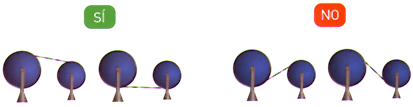
- All legs must have the same inclination angle (if necessary, shortening hooks are fitted).
- In the event of a three-leg octopus, legs must be fastened so that they form a 120º angle with respect to each other.
Asymmetrical Load. If working with a load with asymmetrically placed hooks, the working load limit will be reduced by 50% with respect to the working load that would be the limit under normal conditions.
Cargo lashing by hanging, or with basket slings. The working load limit must be reduced to 80% of nominal value.
Temperature Resistance. The values stated in the table must be considered in order to use 80 Grade Chain Slings at extremely high temperatures.
MAINTENANCE – IDENTIFICATION PLATE
| Chain Temperature | New Working Load Limit in % in relation to the values stated in the Working Load Limit tables under normal conditions. |
| -40 ºC up to + 200 ºC +200 ºC up to + 300 ºC +300 ºC up to + 400 ºC |
100% 90% 75% |
USE
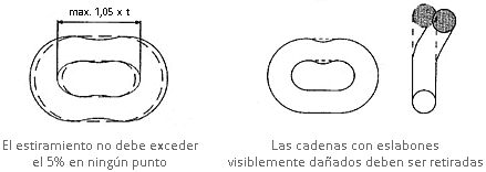
- No lifting with a twisted chain.
- Chains must be shortened solely with shortening hooks. Knots must be avoided.
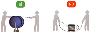
- When handling loads with sharp or cutting tips or edges, the chains must be protected with appropriate padding.
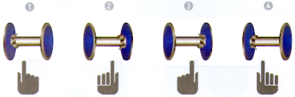
- Hooks must not grip loads with their ends, but with their inner parts.
- Hooks not used during lifting must be fastened to the main ring.
- Make sure that the ring can move freely on the crane hook.
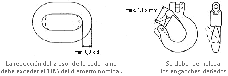
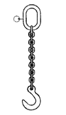
- Replace damaged accessories as soon as they are detected.
- Do not overload the chains; check that the angle inclination is complied with, and, if in doubt, choose a larger chain.
MAINTENANCE – IDENTIFICATION PLATE
Chain slings must be inspected at least once a year by an expert, and load testing (MPI) must be performed at least every three years.
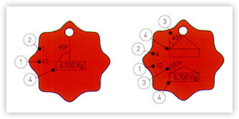
The technical data stated on the plate helps the user to use chain slings properly.
- Chain thickness.
- Number of legs.
- Inclination angle.
- Working load limit.
ADVANTAGES TO CHOOSING OUR SLINGS
- Manufacturing process under IRAM Certification – ISO 9001:2015.
- Rings, connectors, hooks and other accessories, only of certified brands.
- Quality Certificate issued by Izajes y Transmisiones S.A.
Maintenance
| WORKING LOADS | 1 LEG | 2 LEGS | 3 & 4 LEGS | ||
|
CHAIN SLINGS |
 |
 |
 |
||
| mm | ß 0-45º α 0-90º |
ß 45-60º α 90-120º |
ß 0-45º α 0-90º |
ß 45-60º α 90-120º |
|
| 6 | 1.12 | 1.6 | 1.12 | 2.36 | 1.7 |
| 7 | 1.50 | 2.12 | 1.5 | 3.15 | 2.24 |
| 8 | 2.0 | 2.8 | 2.0 | 4.25 | 3.0 |
| 10 | 3.15 | 4.25 | 3.15 | 6.7 | 4.75 |
| 13 | 5.3 | 7.5 | 5.3 | 11.2 | 8.0 |
| 16 | 8.0 | 11.2 | 8.0 | 17.0 | 11.8 |
| 19 | 11.2 | 16.0 | 11.2 | 23.6 | 17.0 |
| 22 | 15.0 | 21.2 | 15.0 | 31.5 | 22.4 |
| 26 | 21.2 | 30.0 | 21.2 | 45.0 | 31.5 |
| 32 | 31.5 | 45.0 | 31.5 | 67.0 | 55 |
| WORKING LOADS | 1 LEG | 2 LEGS | 3 & 4 LEGS | ||
|
CHAIN SLINGS |
|
|
|
||
| mm | ß 0-45º α 0-90º |
ß 45-60º α 90-120º |
ß 0-45º α 0-90º |
ß 45-60º α 90-120º |
|
| 6 | 1.5 | 2.12 | 1.5 | 3.15 | 2.24 |
| 8 | 2.5 | 3.5 | 2.5 | 5.2 | 3.7 |
| 10 | 4.0 | 5.6 | 4 | 8.4 | 6 |
| 13 | 6.7 | 9.5 | 6.7 | 14.0 | 10 |
| 16 | 10 | 14 | 10 | 21.0 | 15 |
| 20 | 16 | 22.4 | 16 | 33.6 | 24 |
| 22 | 19 | 26.9 | 19.0 | 40.3 | 28.5 |
| 26 | 27.0 | 38.2 | 27.0 | 57.3 | 40.5 |