Eyebolts DIN Standards 580/582

Izajes » Productos » Eyebolts DIN Standards 580/582

As always, our Products are here to strengthen your Company.

Eyebolts DIN Standards 580/582


Cáncamos Norma DIN 580 / 582

Metric thread
Dimensions: SWL in kg
1 eyebolt
SWL in kg
2 eyebolts at 45°
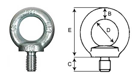
Dimensions in mm
B C D E
M6 70 47 6 13 16 31
M8 140 95 8 13 20 36
M10 230 170 10 17 25 45
M12 340 240 12 20.5 30 53
M16 700 500 14 27 35 62
M20 1,200 830 16 30 40 71
M24 1,800 1,270 20 36 50 90
M27 2,500 1,690 20 38 50 90
M30 3,600 2,600 24 45 60 109
M36 5,100 3,700 28 54 70 128
M42 7,000 5,000 32 63 80 147
M48 8,600 6,100 38 68 90 168
M56 11,500 8,300 42 78 100 187
M64 16,000 11,000 48 90 110 208
British Standard Whitworth (BSW) Thread
Dimensions: SWL in kg
1 eyebolt
SWL in kg
2 eyebolts
Dimensions in mm
B C D E
1/4″ W 70 47 6 13 16 31
5/16″ W 140 95 8 13 20 36
3/8″ W 230 170 10 17 25 45
1/2″ W 340 240 12 20.5 30 53
5/8″ W 700 500 14 27 35 62
3/4″ W 1,200 830 16 30 40 71
1″ W 1,800 1,270 20 36 50 90
1 1/4″ W 3,600 2,600 24 45 60 109
1 1/2″ W 5,100 3,700 28 54 70 128

Recommendations

Unwinding

The coil should be breaked while unwinding so that the wire rope comes out with a certain pressure and does not turn on its axis. This prevents bumps and kinks. If the coil is not equipped with brakes, then an operator should stop it..

Cables de Acero

Transport between coils

When the wire rope is carried from a full coil to an empty one or to a machine drum, this should be done from the upper or lower part of both, but never from the upper part of one coil and the lower part of the other, or vice versa.

Cables de Acero

Wire rope winding

The wire rope winding on the machine drum must be carried out correctly so that there are no spires overlapping and cross-linking, which would crush and distort the cords. The following figures represent the four cases that could effectively take place:

  1. Right torsional wire winding at the upper part of the drum.
    The mooring point should be located on the left side of the drum.
  2. Right torsional wire winding at the lower part of the drum.
    The mooring point should be located on the right side of the drum.
  3. Left torsional wire winding at the lower part of the drum.
    The mooring point should be located on the right side of the drum.
  4. Left torsional wire winding at the lower part of the drum.
    The mooring point should be located on the left side of the drum.

We do not recommend winding the wire around the drum in several layers, but if so, this technique is applied for the first layer of winding.

Cables de Acero

Deflection angle

The deflection angle is that formed by the wire from the first fixed pulley on the edge of the winding drum. It should not exceed 1º 30'.

Cables de Acero

Wire cutting

Cutting with shears or scissors. Before cutting, wires are to be tied together on both sides of the cutting area. The number of ties, the width and the distance between them depend on the wire diameter (see table). It is key to avoid longitudinal tilts among the different cord layers, since, in that case, those which have moved the least will bear the greatest part of the load, and there is the risk of breakage.

Cables de Acero
Tie characteristics
Wire rope diameter No. of ties
on each side
of the cut
Tie
length
Distance
between ties
Wire diameter
rec. iron piece to be
used (mm)
Up to 12 3 12 15 0,5 to 0,8
13 to 20 3 25 40 1 to 1,5
21 to 30 4 40 50 1,2 to 2,2
31 to 40 4 50 50 1,8 to 3
41 to 50 4 75 50 2,2 to 3,2

Recommended cuttings

To cut antitwisting wire ropes, we recommend cutting by electric resistance or by welding.

Cables de Acero

Calibration

For calibration, the measuring device must be properly used.

Cables de Acero

Estamos ONLINE