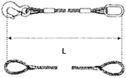
Any sling is defined by:
- The type of wires used (composition, diameter, resistance, etc.).
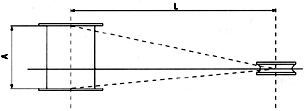
- Their total length (L), including the length of loops or hooks.
- The type of loop manufacturing (with ferrule or braided).
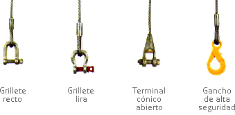
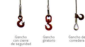
- The type of accessories supplementing it (thimbles, hooks, shackles, turnbuckles, rings, etc.).
| Fiber Core Steel Wire Rope Slings | Loads – Single-Leg Slings | Loads – Multi-Leg Slings | |||||
 |
 |
||||||
| Number of legs, n | – | – | – | 2 legs | 3 & 4 legs | ||
| Inclination angle in relation to the vertical, ß | – | – | – | ß>45º | 45º>ß>60º | ß>45º | 45º>ß>60º |
| Angle between opposite legs, a | – | – | – | a>90º | 90º>a>120º | a>90º | 90º>a>120º |
| Factor to calculate Maximum Working Load (MWL), f=n.cosß | 1 | 0.8 | 2 | 1.4 | 1 | 2.1 | 1.5 |
| Wire diameter | MAXIMUM WORKING LOAD MWL (kg) IRAM 5221, safety factor 5:1 |
||||||
| (Inches) | Balance-loaded Steel Wire Rope Slings | ||||||
| 1/4 | 428 | 342 | 856 | 599 | 428 | 899 | 642 |
| 5/6 | 762 | 610 | 1,524 | 1,067 | 762 | 1,600 | 1,143 |
| 3/8 | 1,101 | 881 | 2,202 | 1,541 | 1,101 | 2,312 | 1,652 |
| 7/16 | 1,475 | 1,180 | 2,950 | 2,065 | 1,475 | 3,098 | 2,212 |
| 1/2 | 2,060 | 1,648 | 4,120 | 2,884 | 2,060 | 4,326 | 3,090 |
| 9/16 | 2,387 | 1,910 | 4,774 | 3,342 | 2,387 | 5,013 | 3,580 |
| 5/8 | 3,121 | 2,497 | 6,242 | 4,369 | 3,121 | 6,554 | 4,682 |
| 3/4 | 4,304 | 3,443 | 8,608 | 6,026 | 4,304 | 9,038 | 6,456 |
| 7/8 | 5,773 | 4,618 | 11,546 | 8,082 | 5,773 | 12,123 | 8,660 |
| 1 | 8,058 | 6,446 | 16,116 | 11,281 | 8,058 | 16,922 | 12,087 |
| 1 1/8 | 9,343 | 7,474 | 18,686 | 13,080 | 9,343 | 19,620 | 14,014 |
| 1 1/4 | 12,199 | 9,759 | 24,398 | 17,079 | 12,199 | 25,618 | 18,298 |
| 1 3/8 | 14,586 | 11,669 | 29,172 | 20,420 | 14,586 | 30,631 | 21,879 |
| 1 1/2 | 17,197 | 13,758 | 34,394 | 24,076 | 17,197 | 36,114 | 25,796 |
| 1 3/4 | 24,113 | 19,290 | 48,226 | 33,758 | 24,113 | 50,637 | 36,170 |
| 2 | 30,988 | 24,790 | 61,976 | 43,383 | 30,988 | 65,075 | 46,482 |
Information on Steel Wire Rope Slings
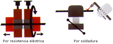
Finishings
MAINTENANCE
- Make sure the sling is suitable for the load. Slings must not be overloaded; the stated MWLs must be complied with.
- The opening angle of the legs must not exceed 120º.
- Examine the sling condition. Never use damaged slings; all damaged slings must be removed from service.
- Sling operations must always be performed with a stable, balanced load.
- Start and finish the operation slowly.
- Do not use slings for internal use without loop protection.
- Do not use elements in the loops that can damage or cut them. Smooth hooks with no edges are recommended.
- Do not drag the slings while moving, nor let them get caught under the load.
- If not provided with proper cut protection, slings must not be used on surfaces with edges.
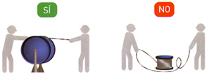
- Slings must always be stored by hanging them by the loops or longitudinally at several points.
- Check with the manufacturer if the slings are used with chemical products or at very high temperatures.
- When breakage of approximately 20% of the wire ropes forming the sling is detected by the naked eye, stop using it.
ADVANTAGES TO CHOOSING OUR SLINGS
- Local Manufacturing.
- Manufacturing process under IRAM Certification – ISO 9001:2015.
- Each sling is uniquely identified for better traceability.
- Fast response to special orders.
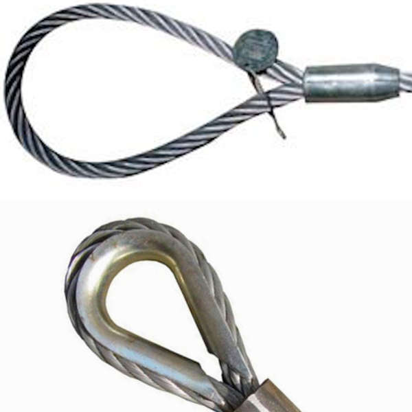
“Folded” eye
(IRAM 5221, Type B)
“Flemish Type” eye
(IRAM 5221, Type A)
Maintenance
- Make sure the sling is suitable for the load. Slings must not be overloaded; the stated MWLs must be complied with.
- The opening angle of the legs must not exceed 120º.
- Examine the sling condition. Never use damaged slings; all damaged slings must be removed from service, as they can only be repaired by qualified personnel.
- Sling operations must always be performed with a stable, balanced load.
- Start and finish the operation slowly.
- Do not use slings for internal use without loop protection.
- Do not use elements in the loops that can damage or cut them. Smooth hooks with no edges are recommended.
- Do not drag the slings while moving, nor let them get caught under the load.
- If not provided with proper cut protection, slings must not be used on surfaces with edges.
- Slings must always be stored by hanging them by the loops or longitudinally at several points.
- Check with the manufacturer if the slings are used with chemical products or at very high temperatures.
- When breakage of approximately 20% of the wire ropes forming the sling is detected by the naked eye, stop using it.
Specifications Data Sheet
-
- Nominal breaking strength of wires used: 1770 n/mm2.
- Wire Factor = 6.25
- Sling Factor = 5:1
- Maximum Working Load (MWL) = breaking strength / safety factor.
| Angle between opposite Legs a |
Angle from vertical ß |
Angle with Factors to calculate MWL | ||
| Number of legs | ||||
| 2 | 3 | 4 | ||
| 90º | ß<=45º | 1.4 | 2.1 | 2.1 |
| 90º<a<=120º | 45º<ß<=60º | 1 | 1.5 | 1.5 |
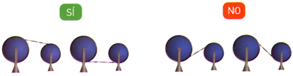
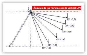
Be careful with angles!
When the legs of a sling do not work vertically, a point to be
considered is that the stress per leg increases as the angle formed
by them from the vertical increases.
To calculate the stress on each leg, its load must be multiplied by
the factor corresponding to the angle according to the attached table.
| Angle Aº | Multiply by: |
| 20º | 1.06 |
| 30º | 1.16 |
| 45º | 1.42 |
| 60º | 2.00 |
| 70º | 2.92 |
| 80º | 5.76 |
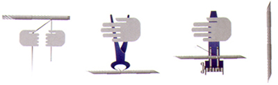
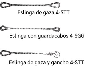
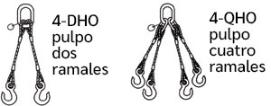
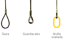
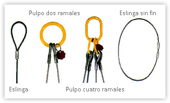
Slings Types
Important Technical Information
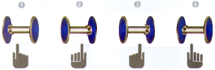
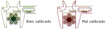
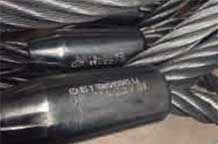
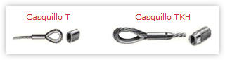
With the iron ferrule, always bear in mind that it is not possible to determine how close the loop is to skipping; this is not so with the T ferrule (where the very existence of the protruding whip proves that pressing is safe), or the TKH ferrule, where for the same reason, the inspection hole ensures that the process is correct.
This is why it is most advisable to check the ferrule throughout the useful life of the sling, in addition to the information on the ferrule itself (it is essential that it is engraved). For this reason, the quality controls with the T and TKH ferrules (used by Izajes to manufacture slings) are much more easily performed, since the end of the wire in the ferrule is visible. With our slings, you will be able to perform this inspection yourself each time you use them; no other manufacturing system enables you to do this since, once the ferrule is closed, no one knows for sure how the wire under it is behaving. This system is used throughout Europe, which accounts for 95% of steel wire rope slings manufactured. The aluminum T and TKH ferrules correspond to the current standard for ferrules, EN 13411-3 (European Community).
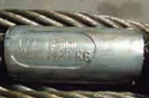
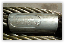 On the steel wire rope slings manufactured by Izajes, the ferrules bear the following engraved information: – Manufacturer identification (IZT = Izajes); – Diameter of the wire, which the sling is made of; – and the Maximum Working Load (MWL). Therefore, in addition to the advantages listed, Izajes identifies its production so that the user can know its origin, in addition to the technical characteristics of the sling. This information accompanies the sling, and is part of it; thus, the sling can always be identified, regardless of the manufacturing certificates issued in this regard. Thus, the tasks of the personnel in charge of safety at your plant are made easier when it comes to controlling any movement requiring safe and reliable slings. The field of application for aluminum ferrules ranges from -40 ºC to 100 ºC. In 90% of the samples in multiple tensile tests, it has been determined that this system offers greater resistance than those made with iron or steel ferrules. For this reason, when ordering a wire rope sling, these various factors have to be considered. Do not hesitate to consult our Technical Department for further information. Quality Department